
How to properly select cables for a photovoltaic system?
The technological advancement in the photovoltaic industry is accelerating at a remarkable pace, with the power output of individual modules increasing significantly, and the current of string arrays also rising accordingly. The current of high-power modules has now exceeded 17A. In terms of system design, the utilization of high-power components and the provision of reasonable reserve space can reduce the initial investment cost and the cost per kilowatt-hour. The cost of AC and DC cables in the system is not insignificant. How should one proceed with the design and selection to minimize costs?
Selection of DC cables
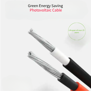
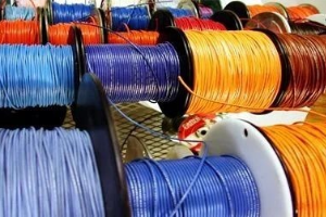
DC cables are installed outdoors. It is generally recommended to choose photovoltaic-specific cables that have undergone irradiation cross-linking. After being irradiated by high-energy electron beams, the molecular structure of the cable insulation material transitions from linear to a three-dimensional network structure, raising the temperature resistance grade from non-cross-linked 70°C to 90°C, 105°C, 125°C, 135°C, or even 150°C. This increases the current-carrying capacity by 15-50% compared to cables of the same specification, enabling them to withstand drastic temperature changes and chemical erosion, and allowing for outdoor use for over 25 years. When selecting DC cables, it is important to choose products from reputable manufacturers with relevant certifications to ensure long-term outdoor use. Currently, the PV1-F1*4 4mm² cable is widely used for photovoltaic DC applications. However, as the current of photovoltaic modules and the power of individual inverters increase, the length of DC cables is also growing, leading to an increased application of 6mm² DC cables.
What is the difference between single-core and multi-Core Cables?
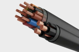
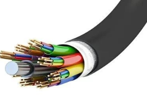
Single-core cables consist of a single conductor within one layer of insulation. Multi-core cables, on the other hand, contain multiple insulated cores. In terms of insulation performance, both single-core and multi-core cables must comply with national standards. The difference between multi-core and single-core cables lies in the fact that the ends of single-core cables are directly grounded, which may induce circulating currents in the metal shielding layer, leading to losses. In contrast, the sum of the currents flowing through the three cores of a multi-core cable is zero, so there is essentially no induced voltage on the metal shielding layer.
Regarding circuit capacity, for the same cross-sectional area, the rated current-carrying capacity of a single-core cable is greater than that of a three-core cable. Single-core cables also have better heat dissipation properties compared to multi-core cables. Under the same load or short-circuit conditions, single-core cables generate less heat than multi-core cables, making them safer in certain scenarios.
In terms of cable installation, multi-core cables are simpler and more convenient to install, as they have inner and multi-layer double protection. For cable bending, single-core cables are easier to bend during installation, but laying them over long distances is more challenging than with multi-core cables. From the perspective of cable termination, single-core cable terminations are easier to install and facilitate easier branching.
Price-wise, multi-core cables are slightly more expensive per unit than single-core cables.
Photovoltaic System Wiring Techniques
The circuitry of a photovoltaic system is divided into two parts: the direct current (DC) section and the alternating current (AC) section. These two parts of the circuit require separate wiring. The DC section connects to the components, while the AC section connects to the power grid. In large and medium-sized power stations, there are numerous DC cables. To facilitate future maintenance, the wire numbers of each cable should be securely fixed. It is essential to separate the strong and weak current lines. If there are signal lines, such as 485 communication lines, they should be routed separately to avoid interference. When wiring, conduits and cable trays should be prepared, and cables should not be left exposed as much as possible. Cables will look more aesthetically pleasing when routed horizontally and vertically. Try to avoid having cable joints in conduits and cable trays, as they can be inconvenient for maintenance. In the entire photovoltaic system, cables are a very important part, and the cost of the system is increasingly high. When designing a power station, we need to save on system costs as much as possible while ensuring the reliable operation of the power station. Therefore, the design and selection of AC and DC cables for the photovoltaic system are particularly important. Moreover, substandard wires and cables not only affect our usage but also directly impact our life safety. Thus, we must keep our eyes open and choose high-quality cables with guaranteed quality. Taking responsibility for our lives and creating a safe environment is not only the goal that Asia Cable has always pursued but also what each of us should do.